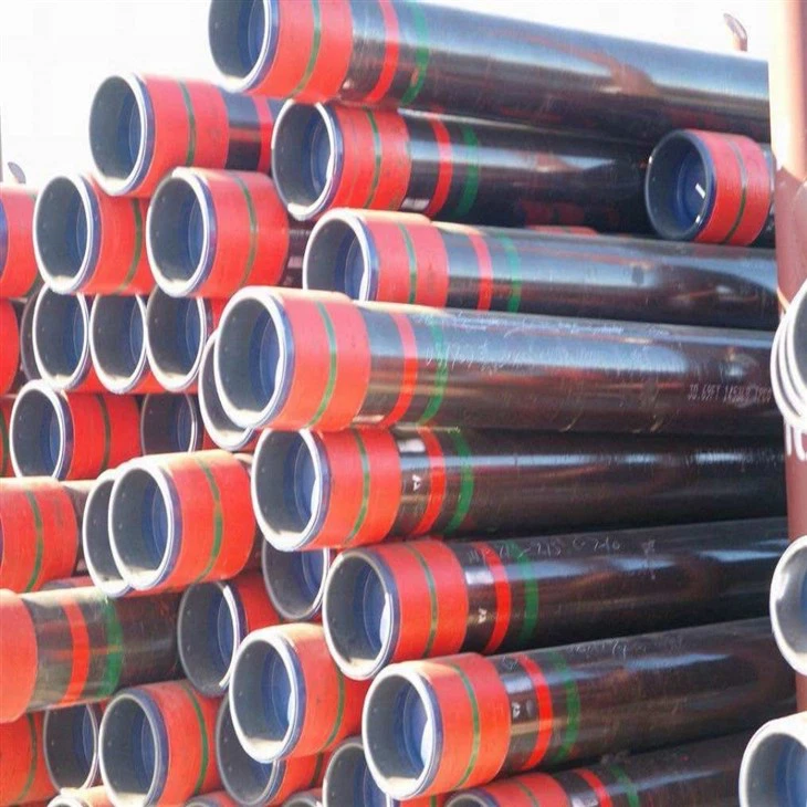
API 5L pipe in grades B, X42, X52, X60, X65 & X70.ANSI / API 5L specifies the manufacture of two product levels (PSL1 and PSL2) of seamless and welded steel pipe for the use of a pipeline in the transportation of petroleum and natural gas.
Professional team

Delivery condition
| PSL | Delivery Condition | Pipe grade |
|---|---|---|
| PSL1 | As-rolled, normalized, normalizing formed | A |
| As-rolled, normalizing rolled, thermomechanical rolled, thermo-mechanical formed, normalizing formed, normalized, normalized and tempered or if agreed Q&T SMLS only | B | |
| As-rolled, normalizing rolled, thermomechanical rolled, thermo-mechanical formed, normalizing formed, normalized, normalized and tempered | X42, X46, X52, X56, X60, X65, X70 | |
| PSL 2 | As-rolled | BR, X42R |
| Normalizing rolled, normalizing formed, normalized or normalized and tempered | BN, X42N, X46N, X52N, X56N, X60N | |
| Quenched and tempered | BQ, X42Q, X46Q, X56Q, X60Q, X65Q, X70Q, X80Q, X90Q, X100Q | |
| Thermomechanical rolled or thermomechanical formed | BM, X42M, X46M, X56M, X60M, X65M, X70M, X80M | |
| Thermomechanical rolled | X90M, X100M, X120M | |
| The suffice (R, N, Q or M) for PSL2 grades, belongs to the steel grade |
Chemical requirements
Chemical Composition for PSL 1 pipe with t ≤ 0.984"
| Steel Grade | Mass fraction, % based on heat and product analyses a,g | ||||||
|---|---|---|---|---|---|---|---|
| C | Mn | P | S | V | Nb | Ti | |
| max b | max b | max | max | max | max | max | |
| Seamless Pipe | |||||||
| A | 0.22 | 0.90 | 0.03 | 0.03 | – | – | – |
| B | 0.28 | 1.20 | 0.03 | 0.03 | c,d | c,d | d |
| X42 | 0.28 | 1.30 | 0.03 | 0.03 | d | d | d |
| X46 | 0.28 | 1.40 | 0.03 | 0.03 | d | d | d |
| X52 | 0.28 | 1.40 | 0.03 | 0.03 | d | d | d |
| X56 | 0.28 | 1.40 | 0.03 | 0.03 | d | d | d |
| X60 | 0.28 e | 1.40 e | 0.03 | 0.03 | f | f | f |
| X65 | 0.28 e | 1.40 e | 0.03 | 0.03 | f | f | f |
| X70 | 0.28 e | 1.40 e | 0.03 | 0.03 | f | f | f |
| Welded Pipe | |||||||
| A | 0.22 | 0.90 | 0.03 | 0.03 | – | – | – |
| B | 0.26 | 1.20 | 0.03 | 0.03 | c,d | c,d | d |
| X42 | 0.26 | 1.30 | 0.03 | 0.03 | d | d | d |
| X46 | 0.26 | 1.40 | 0.03 | 0.03 | d | d | d |
| X52 | 0.26 | 1.40 | 0.03 | 0.03 | d | d | d |
| X56 | 0.26 | 1.40 | 0.03 | 0.03 | d | d | d |
| X60 | 0.26 e | 1.40 e | 0.03 | 0.03 | f | f | f |
| X65 | 0.26 e | 1.45 e | 0.03 | 0.03 | f | f | f |
| X70 | 0.26e | 1.65 e | 0.03 | 0.03 | f | f | f |
| a. Cu ≤ = 0.50% Ni; ≤ 0.50%; Cr ≤ 0.50%; and Mo ≤ 0.15%, b. For each reduction of 0.01% below the specified maximum concentration for carbon, an increase of 0.05% above the specified maximum concentration for Mn is permissible, up to a maximum of 1.65% for grades ≥ L245 or B, but ≤ L360 or X52; up to a maximum of 1.75% for grades > L360 or X52, but < L485 or X70; and up to a maximum of 2.00% for grade L485 or X70., c. Unless otherwise agreed NB + V ≤ 0.06%, d. Nb + V + TI ≤ 0.15%, e. Unless otherwise agreed., f. Unless otherwise agreed, NB + V = Ti ≤ 0.15%, g. No deliberate addition of B is permitted and the residual B ≤ 0.001% |
|||||||
Chemical Composition for PSL 2 pipe with t ≤ 0.984"
| Steel Grade | Mass fraction, % based on heat and product analyses | Carbon Equiv a | |||||||||||||||||||
|---|---|---|---|---|---|---|---|---|---|---|---|---|---|---|---|---|---|---|---|---|---|
| C | Si | Mn | P | S | V | Nb | Ti | Other | CE IIW | CE Pcm | |||||||||||
| max b | max | max b | max | max | max | max | max | max | max | ||||||||||||
| Seamless and Welded Pipe | |||||||||||||||||||||
| BR | 0.24 | 0.40 | 1.20 | 0.025 | 0.015 | c | c | 0.04 | e,l | 0.43 | 0.25 | ||||||||||
| X42R | 0.24 | 0.40 | 1.20 | 0.025 | 0.015 | 0.06 | 0.05 | 0.04 | e,l | 0.43 | 0.25 | ||||||||||
| BN | 0.24 | 0.40 | 1.20 | 0.025 | 0.015 | c | c | 0.04 | e,l | 0.43 | 0.25 | ||||||||||
| X42N | 0.24 | 0.40 | 1.20 | 0.025 | 0.015 | 0.06 | 0.05 | 0.04 | e,l | 0.43 | 0.25 | ||||||||||
| X46N | 0.24 | 0.40 | 1.40 | 0.025 | 0.015 | 0.07 | 0.05 | 0.04 | d,e,l | 0.43 | 0.25 | ||||||||||
| X52N | 0.24 | 0.45 | 1.40 | 0.025 | 0.015 | 0.10 | 0.05 | 0.04 | d,e,l | 0.43 | 0.25 | ||||||||||
| X56N | 0.24 | 0.45 | 1.40 | 0.025 | 0.015 | 0.10f | 0.05 | 0.04 | d,e,l | 0.43 | 0.25 | ||||||||||
| X60N | 0.24f | 0.45f | 1.40f | 0.025 | 0.015 | 0.10f | 0.05f | 0.04f | g,h,l | As agreed | |||||||||||
| BQ | 0.18 | 0.45 | 1.40 | 0.025 | 0.015 | 0.05 | 0.05 | 0.04 | e,l | 0.43 | 0.25 | ||||||||||
| X42Q | 0.18 | 0.45 | 1.40 | 0.025 | 0.015 | 0.05 | 0.05 | 0.04 | e,l | 0.43 | 0.25 | ||||||||||
| X46Q | 0.18 | 0.45 | 1.40 | 0.025 | 0.015 | 0.05 | 0.05 | 0.04 | e,l | 0.43 | 0.25 | ||||||||||
| X52Q | 0.18 | 0.45 | 1.50 | 0.025 | 0.015 | 0.05 | 0.05 | 0.04 | e,l | 0.43 | 0.25 | ||||||||||
| X56Q | 0.18 | 0.45f | 1.50 | 0.025 | 0.015 | 0.07 | 0.05 | 0.04 | e,l | 0.43 | 0.25 | ||||||||||
| X60Q | 0.18f | 0.45f | 1.70f | 0.025 | 0.015 | g | g | g | h,l | 0.43 | 0.25 | ||||||||||
| X65Q | 0.18f | 0.45f | 1.70f | 0.025 | 0.015 | g | g | g | h,l | 0.43 | 0.25 | ||||||||||
| X70Q | 0.18f | 0.45f | 1.80f | 0.025 | 0.015 | g | g | g | h,l | 0.43 | 0.25 | ||||||||||
| X80Q | 0.18f | 0.45f | 1.90f | 0.025 | 0.015 | g | g | g | i,j | As agreed | |||||||||||
| X90Q | 0.16f | 0.45f | 1.90 | 0.020 | 0.010 | g | g | g | j,k | As agreed | |||||||||||
| X100Q | 0.16f | 0.45f | 1.90 | 0.020 | 0.010 | g | g | g | j,k | As agreed | |||||||||||
| Welded Pipe | |||||||||||||||||||||
| BM | 0.22 | 0.45 | 1.20 | 0.025 | 0.015 | 0.05 | 0.05 | 0.04 | e,l | 0.43 | 0.25 | ||||||||||
| X42M | 0.22 | 0.45 | 1.30 | 0.025 | 0.015 | 0.05 | 0.05 | 0.04 | e,l | 0.43 | 0.25 | ||||||||||
| X46M | 0.22 | 0.45 | 1.30 | 0.025 | 0.015 | 0.05 | 0.05 | 0.04 | e,l | 0.43 | 0.25 | ||||||||||
| X52M | 0.22 | 0.45 | 1.40 | 0.025 | 0.015 | d | d | d | e,l | 0.43 | 0.25 | ||||||||||
| X56M | 0.22 | 0.45f | 1.40 | 0.025 | 0.015 | d | d | d | e,l | 0.43 | 0.25 | ||||||||||
| X60M | 0.12f | 0.45f | 1.60f | 0.025 | 0.015 | g | g | g | h,l | 0.43 | 0.25 | ||||||||||
| X65M | 0.12f | 0.45f | 1.60f | 0.025 | 0.015 | g | g | g | h,l | 0.43 | 0.25 | ||||||||||
| X70M | 0.12f | 0.45f | 1.70f | 0.025 | 0.015 | g | g | g | h,l | 0.43 | 0.25 | ||||||||||
| X80M | 0.12f | 0.45f | 1.85f | 0.025 | 0.015 | g | g | g | i,j | .043f | 0.25 | ||||||||||
| X90M | 0.1 | 0.55f | 2.10f | 0.02 | 0.01 | g | g | g | i,j | – | 0.25 | ||||||||||
| X100M | 0.1 | 0.55f | 2.10f | 0.02 | 0.01 | g | g | g | i,j | – | 0.25 | ||||||||||
| a. SMLS t>0.787", CE limits shall be as agreed. The CEIIW limits applied fi C > 0.12% and the CEPcm limits apply if C ≤ 0.12%, b. For each reduction of 0.01% below the specified maximum for C, an increase of 0.05% above the specified maximum for Mn is permissible, up to a maximum of 1.65% for grades ≥ L245 or B, but ≤ L360 or X52; up to a maximum of 1.75% for grades > L360 or X52, but < L485 or X70; up to a maximum of 2.00% for grades ≥ L485 or X70, but ≤ L555 or X80; and up to a maximum of 2.20% for grades > L555 or X80., c. Unless otherwise agreed Nb = V ≤ 0.06%, d. Nb = V = Ti ≤ 0.15%, e. Unless otherwise agreed, Cu ≤ 0.50%; Ni ≤ 0.30% Cr ≤ 0.30% and Mo ≤ 0.15%, f. Unless otherwise agreed, g. Unless otherwise agreed, Nb + V + Ti ≤ 0.15%, h. Unless otherwise agreed, Cu ≤ 0.50% Ni ≤ 0.50% Cr ≤ 0.50% and MO ≤ 0.50%, i. Unless otherwise agreed, Cu ≤ 0.50% Ni ≤ 1.00% Cr ≤ 0.50% and MO ≤ 0.50%, j. B ≤ 0.004%, k. Unless otherwise agreed, Cu ≤ 0.50% Ni ≤ 1.00% Cr ≤ 0.55% and MO ≤ 0.80%, l. For all PSL 2 pipe grades except those grades with footnotes j noted, the following applies. Unless otherwise agreed no intentional addition of B is permitted and residual B ≤ 0.001%. |
|||||||||||||||||||||
Mechanical properties
| Pipe Grade | Tensile Properties – Pipe Body of SMLS and Welded Pipes PSL 1 | Seam of Welded Pipe | ||
|---|---|---|---|---|
| Yield Strength a | Tensile Strength a | Elongation | Tensile Strength b | |
| Rt0,5 PSI Min | Rm PSI Min | (in 2in Af % min) | Rm PSI Min | |
| A | 30,500 | 48,600 | c | 48,600 |
| B | 35,500 | 60,200 | c | 60,200 |
| X42 | 42,100 | 60,200 | c | 60,200 |
| X46 | 46,400 | 63,100 | c | 63,100 |
| X52 | 52,200 | 66,700 | c | 66,700 |
| X56 | 56,600 | 71,100 | c | 71,100 |
| X60 | 60,200 | 75,400 | c | 75,400 |
| X65 | 65,300 | 77,500 | c | 77,500 |
| X70 | 70,300 | 82,700 | c | 82,700 |
| a. For intermediate grade, the difference between the specified minimum tensile strength and the specified minimum yield for the pipe body shall be as given for the next higher grade. | ||||
| b. For the intermediate grades, the specified minimum tensile strength for the weld seam shall be the same as determined for the body using foot note a. | ||||
| c. The specified minimum elongation, Af, expressed in percent and rounded to the nearest percent, shall be determined using the following equation: | ||||
| Where C is 1 940 for calculation using Si units and 625 000 for calculation using USC units | ||||
| Axc is the applicable tensile test piece cross-sectional area, expressed in square millimeters (square inches) , as follows | ||||
| – For circular cross-section test pieces, 130mm2 (0.20 in2) for 12.7 mm (0.500 in) and 8.9 mm (.350 in) diameter test pieces; and 65 mm2 (0.10 in2) for 6.4 mm (0.250in) diameter test pieces. | ||||
| – For full-section test pieces, the lesser of a) 485 mm2 (0.75 in2) and b) the cross-sectional area of the test piece, derived using the specified outside diameter and the specified wall thickness of the pipe, rounded to the nearest 10 mm2 (0.10in2) | ||||
| – For strip test pieces, the lesser of a) 485 mm2 (0.75 in2) and b) the cross-sectional area of the test piece, derived using the specified width of the test piece and the specified wall thickness of the pipe, rounded to the nearest 10 mm2 (0.10in2) | ||||
| U is the specified minimum tensile strength, expressed in megapascals (pounds per square inch) | ||||
| Pipe Grade | Tensile Properties – Pipe Body of SMLS and Welded Pipes PSL 2 | Seam of Welded Pipe | |||||
|---|---|---|---|---|---|---|---|
| Yield Strength a | Tensile Strength a | Ratio a,c | Elongation | Tensile Strength d | |||
| Rt0,5 PSI Min | Rm PSI Min | R10,5IRm | (in 2in) | Rm (psi) | |||
| Af % | |||||||
| Minimum | Maximum | Minimum | Maximum | Maximum | Minimum | Minimum | |
| BR, BN,BQ,BM | 35,500 | 65,300 | 60,200 | 95,000 | 0.93 | f | 60,200 |
| X42,X42R,X2Q,X42M | 42,100 | 71,800 | 60,200 | 95,000 | 0.93 | f | 60,200 |
| X46N,X46Q,X46M | 46,400 | 76,100 | 63,100 | 95,000 | 0.93 | f | 63,100 |
| X52N,X52Q,X52M | 52,200 | 76,900 | 66,700 | 110,200 | 0.93 | f | 66,700 |
| X56N,X56Q,X56M | 56,600 | 79,000 | 71,100 | 110,200 | 0.93 | f | 71,100 |
| X60N,X60Q,S60M | 60,200 | 81,900 | 75,400 | 110,200 | 0.93 | f | 75,400 |
| X65Q,X65M | 65,300 | 87,000 | 77,600 | 110,200 | 0.93 | f | 76,600 |
| X70Q,X65M | 70,300 | 92,100 | 82,700 | 110,200 | 0.93 | f | 82,700 |
| X80Q,X80M | 80,.500 | 102,300 | 90,600 | 119,700 | 0.93 | f | 90,600 |
| a. For intermediate grade, refer to the full API5L specification. | |||||||
| b. for grades > X90 refer to the full API5L specification. | |||||||
| c. This limit applies for pies with D> 12.750 in | |||||||
| d. For intermediate grades, the specified minimum tensile strength for the weld seam shall be the same value as was determined for the pipe body using foot a. | |||||||
| e. for pipe requiring longitudinal testing, the maximum yield strength shall be ≤ 71,800 psi | |||||||
| f. The specified minimum elongation, Af, expressed in percent and rounded to the nearest percent, shall be determined using the following equation: | |||||||
| Where C is 1 940 for calculation using Si units and 625 000 for calculation using USC units | |||||||
| Axc is the applicable tensile test piece cross-sectional area, expressed in square millimeters (square inches) , as follows | |||||||
| – For circular cross-section test pieces, 130mm2 (0.20 in2) for 12.7 mm (0.500 in) and 8.9 mm (.350 in) diameter test pieces; and 65 mm2 (0.10 in2) for 6.4 mm (0.250in) diameter test pieces. | |||||||
| – For full-section test pieces, the lesser of a) 485 mm2 (0.75 in2) and b) the cross-sectional area of the test piece, derived using the specified outside diameter and the specified wall thickness of the pipe, rounded to the nearest 10 mm2 (0.10in2) | |||||||
| – For strip test pieces, the lesser of a) 485 mm2 (0.75 in2) and b) the cross-sectional area of the test piece, derived using the specified width of the test piece and the specified wall thickness of the pipe, rounded to the nearest 10 mm2 (0.10in2) | |||||||
| U is the specified minimum tensile strength, expressed in megapascals (pounds per square inch | |||||||
| g. Lower values fo R10,5IRm may be specified by agreement | |||||||
| h. for grades > x90 refer to the full API5L specification. | |||||||
Products Application
The API 5L welded line pipe is a fundamental component of modern infrastructure, specifically designed for the transportation of oil, gas, and other fluids. Its applications are vast and critical to the global energy and industrial sectors.
1. Oil and Gas Transmission Pipelines (The Primary Application)
This is the core purpose for which API 5L was developed. These pipelines form the vast, continent-spanning networks that move hydrocarbons from production fields to refineries, distribution centers, and ultimately to consumers.
Gathering Lines: These are smaller-diameter pipes that collect crude oil or natural gas from multiple wellheads in a field and transport it to a central collection or processing facility.
Transmission/Trunk Lines: These are the long-distance, large-diameter "highways" of the energy industry. They transport processed oil or natural gas over hundreds or thousands of miles across countries and continents.
Distribution Lines: The final leg of the network, consisting of smaller-diameter pipes that deliver natural gas to local communities, businesses, and individual homes.
Why API 5L is used: Its standardized strength grades (e.g., X42, X52, X65, X70, X80), strict chemical composition, and rigorous mechanical testing ensure it can handle the high pressures, volatile contents, and environmental stresses encountered over decades of operation.
2. Natural Gas Distribution Networks
A subset of the above, but worth highlighting due to its importance for public utilities. Welded API 5L pipe is used for both high-pressure main lines and medium-pressure distribution lines within cities and towns, ensuring a safe and reliable supply of gas for heating and cooking.
3. Water Transmission and Supply
While often subject to additional coatings for corrosion prevention, large-diameter API 5L pipes are extensively used for:
Raw Water Mains: Transporting water from reservoirs, rivers, or treatment plants.
Potable Water Lines: Serving as the primary arteries for municipal water supply systems due to their strength and reliability for high-pressure applications.
Industrial Water Supply: Delivering large volumes of water to power plants, manufacturing facilities, and agricultural irrigation projects.
4. Carbon Dioxide (CO2) Transportation
This is a growing and critical application, particularly for:
Enhanced Oil Recovery (EOR): CO2 is injected into aging oil fields to increase pressure and force more oil to the surface.
Carbon Capture, Utilization, and Storage (CCUS): Captured CO2 from industrial processes (e.g., power plants, cement factories) is compressed and transported via pipeline to be stored permanently underground in geological formations.
Why API 5L is used: Transporting dense-phase CO2 presents unique challenges (e.g., corrosion in the presence of water). API 5L pipes can be manufactured from specially selected grades and with stringent toughness requirements to ensure safe containment.
5. Slurry Pipelines
These pipelines transport a mixture of solid particles (like coal, iron ore, or copper concentrate) suspended in a liquid (usually water).
Mining Industry: To move mined minerals from remote mining sites to processing plants or ports over long distances. This is often more economical and environmentally friendly than truck or rail transport.
Why API 5L is used: The internal abrasion from solid particles is extreme. API 5L pipes specified for slurry service are often made from higher-strength grades and can be supplied with special abrasion-resistant linings or increased wall thickness to extend service life.
6. Industrial Applications
Within large industrial complexes, API 5L pipe is used for intra-plant piping systems that require high strength and reliability, such as:
Steam Lines: Transporting high-pressure steam for power generation and process heating.
Process Lines: Moving various process fluids, chemicals, and feedstocks between different units within a refinery, chemical plant, or petrochemical facility.
While API 5L welded pipe is the workhorse for long-distance, large-diameter transmission, API 5L seamless line pipe is the specialist, chosen for applications where its unique properties are critical for safety, performance, and reliability.
The key difference lies in the manufacturing process: seamless pipe is formed from a solid billet of steel that is pierced and stretched into a hollow pipe, meaning it has no longitudinal weld seam. This fundamental difference dictates its applications.
Here are the primary applications of API 5L seamless line pipe:
1. High-Pressure, High-Hazard Service
This is the most significant application area for seamless pipe. The absence of a weld seam eliminates the most common potential point of failure (e.g., weld defects, inconsistencies in the heat-affected zone).
Sour Service (H₂S Environments): In oil and gas fields containing hydrogen sulfide, the risk of Sulfide Stress Cracking (SSC) is high. Seamless pipe, with its more homogeneous and controlled microstructure, offers superior resistance to this catastrophic form of cracking compared to welded pipe, where the weld and heat-affected zone can be vulnerable.
Offshore Platforms & Subsea Pipelines: These environments are incredibly demanding, with high external pressures, corrosive seawater, and difficult inspection and repair. Seamless pipe is often specified for critical flow lines, risers (which connect the seabed to the platform), and jumper lines due to its guaranteed integrity and high pressure rating.
Gas Injection & CO₂ Flooding Lines: Used in Enhanced Oil Recovery (EOR), these lines operate at extremely high pressures. The uniformity of wall thickness and strength around the entire circumference of seamless pipe makes it the default choice for such critical, high-pressure services.
2. Small-Diameter Flow Lines and Gathering Lines
While large-diameter transmission pipes are welded, the smaller-diameter pipes that connect individual wellheads to processing facilities are often seamless.
Reason: For smaller diameters (e.g., 2" to 12"), the cost difference between seamless and welded pipe diminishes. Given the often harsh and variable pressures and fluids coming directly from the wellhead (which may be sour, erosive, or high-pressure), operators opt for the added safety and reliability of seamless pipe.
3. Critical Process Piping within Facilities
Inside refineries, petrochemical plants, gas processing plants, and compressor stations, you will find extensive use of seamless API 5L pipe.
Applications: It is used for high-pressure transfer lines, feedstock lines, compressor discharge lines, and fuel gas lines. The compact layout of a plant involves many bends, twists, and connections, requiring pipes with consistent strength in all directions. The reliability of seamless pipe is paramount in these congested plants where a failure would be catastrophic.
4. Applications with Severe Bending or Coiling
Seamless pipe has uniform mechanical properties around its entire circumference.
Directional Drilling (HDD): For Horizontal Directional Drilling installations, the pipe must endure significant bending stresses during pullback. A seamless pipe is less likely to develop issues during this process.
Coiled Tubing: While not API 5L, the principle is the same. Seamless tubing is essential for applications where the pipe is spooled onto a giant reel and uncoiled for downhole operations because it lacks a weld seam that could crack under repeated bending stress.
5. Erosive and Abrasive Services
Although welded pipe can handle abrasion (often with linings), the perfectly smooth and consistent internal surface of seamless pipe provides better resistance to erosion from sand, proppant, or other fine particulates in the flow stream without the risk of erosion starting at a minute weld imperfection.
Key Advantages of Seamless Pipe Driving These Applications:
No Weld Seam: Eliminates the risk of weld defects and provides homogeneous strength around the entire circumference.
Superior Strength Under Pressure: Generally capable of handling higher pressures and more extreme load conditions.
Uniform Wall Thickness: Provides more predictable performance under high stress and is less prone to failure from erosion.
Better Ovality and Dimensional Consistency: Often has a more perfect roundness, which is beneficial for making critical connections in pressure systems.
Summary Table: Welded vs. Seamless API 5L
| Feature | API 5L Welded Pipe | API 5L Seamless Pipe |
|---|---|---|
| Primary Application | Long-distance, large-diameter transmission | High-pressure, critical, hazardous service |
| Key Advantage | Cost-effective for large sizes | Superior integrity & pressure rating |
| Sizes | Very large diameters (e.g., 24" to 48"+) | Generally smaller diameters (up to ~24") |
| Cost | Lower cost for large diameters | Higher cost due to complex manufacturing |
| Critical Factor | The quality and integrity of the weld seam | Homogeneity of the steel throughout |
In conclusion, API 5L seamless line pipe is the premium choice for the most demanding, high-risk, and high-pressure applications in the energy industry and beyond, where failure is not an option. Its use is dictated by safety cases and engineering specifications that prioritize inherent material reliability over cost.


Hot Tags: api 5l gr.b psl 1, China api 5l gr.b psl 1 manufacturers, suppliers, factory


